IMP-8 EECA Description
The Electrostatic Energy-Charge Analyzer (EECA) is the University
of Maryland experiment on the IMP-8
Satellite. It uses electrostatic deflection and total energy measurements to
determine the ionic charge and energy of particles in the range of approximately
100 to 1000 keV/charge.
- Determining an ion's charge
- The deflection of an ion traveling through any electrostatic field is a function
only of the ratio of its energy to its charge. Thus from a simultaneous measurement
of a particle's deflection in a known electrostatic field and its total kinetic energy,
one can also determine its charge.
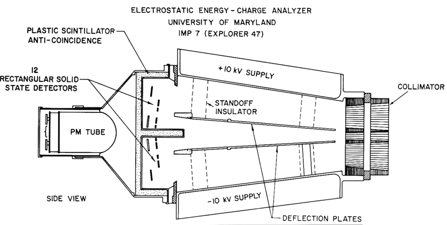
- Deflecting the particles
- In the EECA experiment, the deflection fields are created by applying voltages
to two flat non-parallel plates, mounted on stand-off insulators in a grounded cavity.
One plate is maintained at a potential of +14.5 kV relative to the ground plate,
the other at +3.5 kV. The three field regions created in the deflection cavity have
potential differences of 14.5 kV (top), 11 kV (center), and 3.5 kV (bottom), corresponding
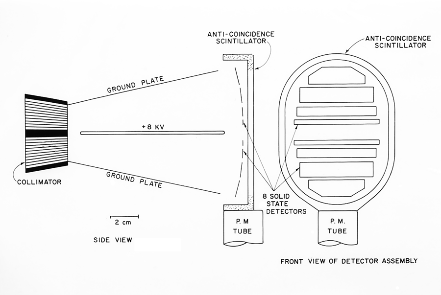
to fields of 7.25 kV/cm, 11 kV/cm, and 1.75 kV/cm, respectively. A passive collimator
at the entrance of the cavity defines the arrival directions of incoming particles.
- Measuring the deflection
- A charged particle entering the sensor is deflected in one of the these three
field regions. Its deflection is determined by the location of the one solid state
detector in the array which is triggered as the particle strikes its surface while
exiting the cavity. At the same time this detector measures the total energy of the
particle by pulse height analysis of its output signal. The energy per charge range
of each detector is defined by its position and width. The rates are determined by
simply counting the number of particles which trigger each of the detectors. The
charge and finer energy resolution for each detector is achieved by pulse height
analysis of the signals from that detector.
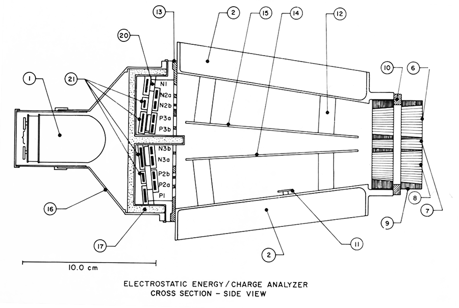
- Detector construction - front
- The front of the detector array consists of seven thin silicon surface barrier
detectors designated P1 to P4 and P6 to P8 in order of
increasing energy-per-charge of the particles able to reach them. The detector P5
is covered with aluminum foil just thick enough to stop protons deflected to it.
It is identical to P2 and P6, and its purpose is to measure the shape
and intensity of the background spectrum. Continuous monitoring of the background
spectrum is essential because the background spectral shape changes during different
solar flare events.
- Detector construction - back
- Behind this front layer is an array of six thick Si (Li) detectors, positioned
so that any particle which penetrates one of the front detectors must also strike
one of these. All back detectors are wired in parallel and are referred to collectively
as B. The requirement for pulse height analysis of a P detector Pn
is an anti-coincidence of Pn and B since positive ions reaching these
P detectors will be stopped in them. The B anti-coincidence also helps to
reduce background due to penetrating particles.
- Detector construction - the scintillator
- A plastic anti-coincidence scintillator surrounds the detectors, preventing analysis
of high energy penetrating particles and further reducing background. The scintillator
provides greater than 2 pi anti-coincidence protection. In addition, the scintillator
counting rate is a measure of the proton spectrum at high energies. The A1
scintillator responds to protons with energies above 40 MeV, and the A2
scintillator responds to protons above 20 MeV. Both of these have very large geometrical
factors (~1100 and 700 cm2 sr., respectively).
Table 1
Table 1 lists the
response factors of our primary detectors. The Flux Conversion Factor, when multiplied
with the observed counting rate, yields the differential intensity in units of
(particles/cm2-sec-sr-keV/e). Note: P5 is a background-measuring rate
as described in the text above.
|
Detector
|
Dominant
Species
|
Energy
Range
(keV/e)
|
Average
Energy
(keV/e)
|
Flux Conversion
Factor
|
| P2 |
He++ |
74-114 |
92 |
1.70 |
| P3 |
H+ |
148-249 |
190 |
0.66 |
| P4 |
H+ |
175-254 |
210 |
1.14 |
| P5 |
* |
* |
* |
* |
| P6 |
H+ |
406-596 |
490 |
0.75 |
| P7 |
H+ |
663-1088 |
850 |
0.14 |
| P7' |
He++ |
663-1088 |
850 |
0.15 |
| P8 |
H+ |
825-1232 |
1010 |
0.27 |
IMP-8-EECA_DESC.HTML last modified on 8/30/12 at 1:05 PM by sel